
The Smart Mesh
The Smart Mesh is an extension of the simple mesh. It creates a fully connected, flexible mesh audio network, using JackTrip:
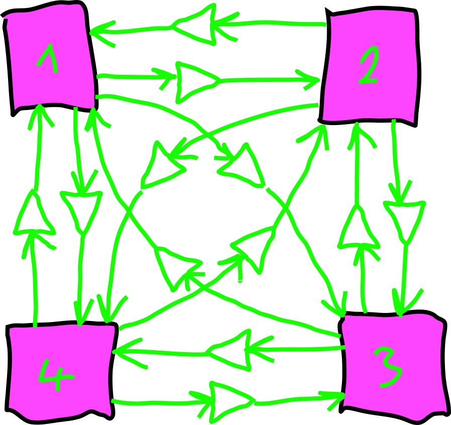
Four Access Points in a 'smart' mesh.
In this configuration, audio signals can be sent from every node to every node with a specific gain. Each of the Access Points [1,2,3,4] can manage where to send signals and which signals to receive.
Step 1: Launch Jack with Autoconnect Restrictions
In order to be in full control of the Jack-connections, we need to add the following flags to restrict all autoconnect requests from new clients:
Read the section on using JACK Audio for the full list of arguments we need.
Step 2-3: Follow the Simple Mesh Example
Follow all steps in the Simple Mesh example to get the JackTrip server and clients running on the APs.
Step 4: The SC Mixer
To route signals from each AP to al other APs, we need to increase the number of SC input and output buses needs to be increased. With N=11 peers we want N outputs - one to the speaker the PI is connected to, and one output to each JackTrip client:
The Control Buses
After booting the local server, we create a NxN control-bus routing matrix. This is realized through an array of multichannel buses:
The Send-SynthDef
This SynthDef takes one input signal (from JackTrip or the analog input) and routes it to all outputs with individual gains:
SynthDef(\mesh_send,{
    |
    inbus,
    outbus,
    gainbus
    |
    Out.ar(outbus, SoundIn.ar(Array.fill(12,inbus)) * In.kr(gainbus,12));
}).send;
As shown in the following figure, the mesh_send is only prcessing one input:
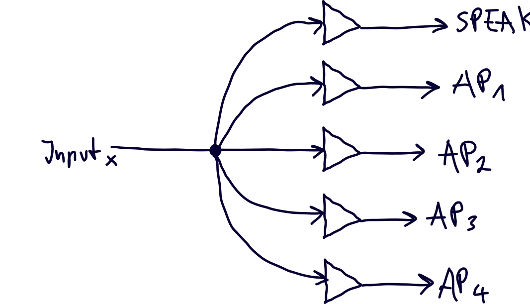
Signal flow for the mesh_send with 4 APs.
The Mixer
Our mixer consists of multiple Send-Synths - one for each input signal. We create an array of N=12 mesh_sends, each with the proper index for input and control bus. Every send node will get an individual input and an individual element from ~gain_BUS - but they all output their signals to the same 12 outputs of SC:
Step 5: Connecting the Jack-Clients
If the SC server has been properly cofigured and booted, the JackTrip clients can be connected. The following image shows the connections on AP1 for a total of 4 Access Points:
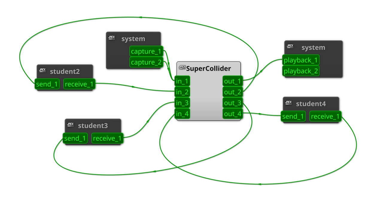
Jack routings for a smart mesh with 4 APs.
Step 6: Set Routing Gains
Once all components are running and everything has been connected, the values of the control buses on each node can be set, to create all possible forms of configurations. Since there is no aditional processing (delay, feedback, ...) in the chain, we have to avoid feedbacks.
If AP1 from the previous figure wants to send its local audio input (mic, instrument) to AP2, the following bus gains have to be set:
If AP1 wants to send its local input to all other nodes and the local output (loudspeaker), it can use the following command: