
Force Sensing Linear Potentiometer
Force-sensing linear potentiometers (FSLPs) combine the typical force-sensing capabilities of FSRs and in addition sense the position of the force. This combination offers great expressive possibilities with a simple setup.
Breadboard Wiring
On the breadboard, the FSLP needs only one addition resistor of $4.7k\Omega$:
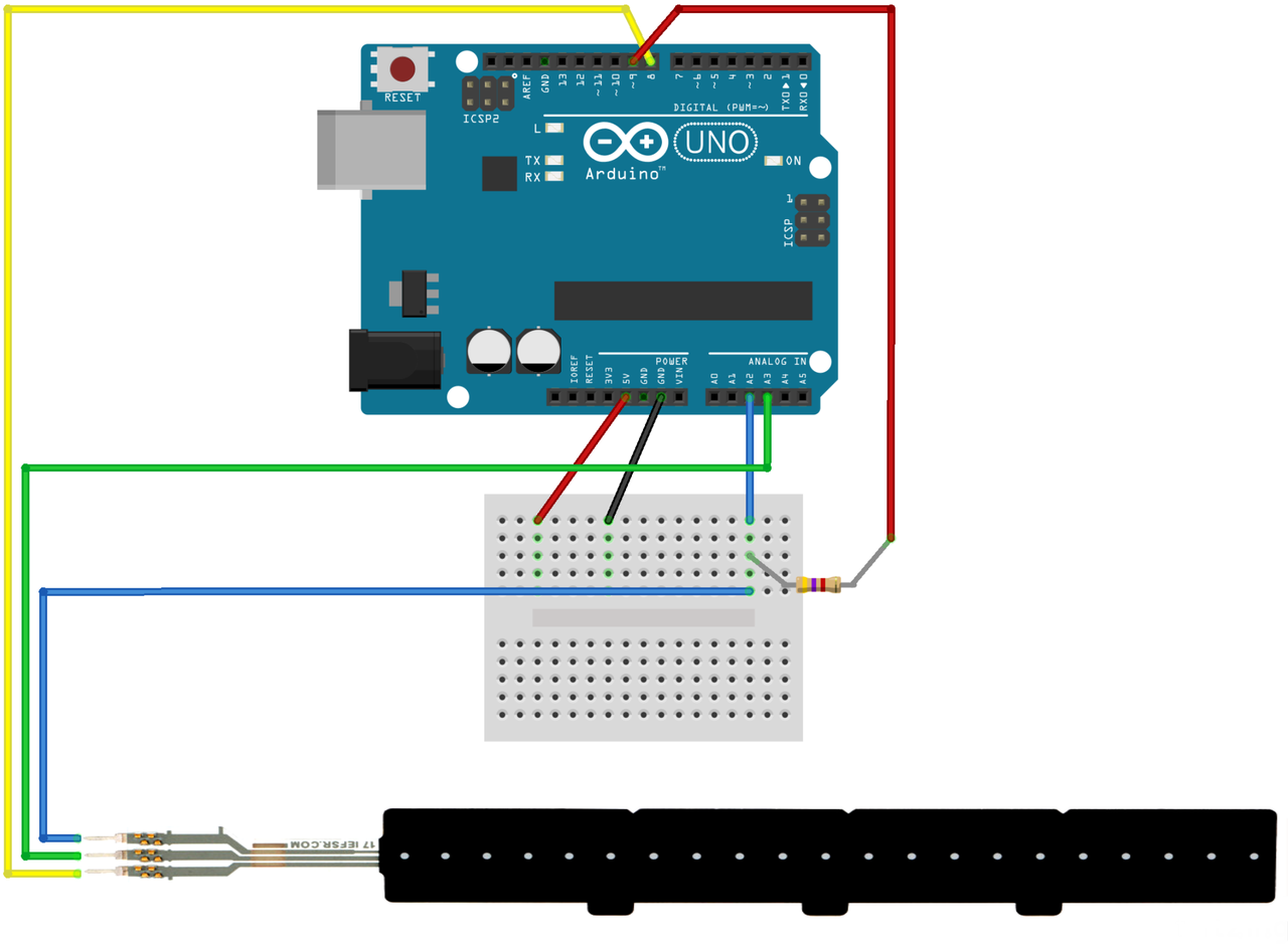
Figure: Arduino breadboard wiring.
Arduino Code
The following example is adopted from the Pololu website.
In the main loop, two dedicated functions fslpGetPressure and fslpGetPosition are used to read
force and position, respectively.
To send both values in one 'array', three individual Serial.print() commands are
used, followed by a Serial.println(). This sends a return character, allowing the
receiver to detect the end of a message block:
const int fslpSenseLine = A2;
const int fslpDriveLine1 = 8;
const int fslpDriveLine2 = A3;
const int fslpBotR0 = 9;

void setup()
{
  Serial.begin(9600);
  delay(250);
}

void loop()
{
  int pressure, position;

  pressure = fslpGetPressure();

  if (pressure == 0)
  {
    position = 0;
  }
  else
  {
    position = fslpGetPosition();
  }

  Serial.print(pressure);
  Serial.print(" ");
  Serial.print(position);
  Serial.println();

  delay(20);
}

// This function follows the steps described in the FSLP
// integration guide to measure the position of a force on the
// sensor.  The return value of this function is proportional to
// the physical distance from drive line 2, and it is between
// 0 and 1023.  This function does not give meaningful results
// if fslpGetPressure is returning 0.
int fslpGetPosition()
{
  // Step 1 - Clear the charge on the sensor.
  pinMode(fslpSenseLine, OUTPUT);
  digitalWrite(fslpSenseLine, LOW);

  pinMode(fslpDriveLine1, OUTPUT);
  digitalWrite(fslpDriveLine1, LOW);

  pinMode(fslpDriveLine2, OUTPUT);
  digitalWrite(fslpDriveLine2, LOW);

  pinMode(fslpBotR0, OUTPUT);
  digitalWrite(fslpBotR0, LOW);

  // Step 2 - Set up appropriate drive line voltages.
  digitalWrite(fslpDriveLine1, HIGH);
  pinMode(fslpBotR0, INPUT);
  pinMode(fslpSenseLine, INPUT);

  // Step 3 - Wait for the voltage to stabilize.
  delayMicroseconds(10);

  // Step 4 - Take the measurement.
  analogReset();
  return analogRead(fslpSenseLine);
}

// This function follows the steps described in the FSLP
// integration guide to measure the pressure on the sensor.
// The value returned is usually between 0 (no pressure)
// and 500 (very high pressure), but could be as high as
// 32736.
int fslpGetPressure()
{
  // Step 1 - Set up the appropriate drive line voltages.
  pinMode(fslpDriveLine1, OUTPUT);
  digitalWrite(fslpDriveLine1, HIGH);

  pinMode(fslpBotR0, OUTPUT);
  digitalWrite(fslpBotR0, LOW);

  pinMode(fslpSenseLine, INPUT);

  pinMode(fslpDriveLine2, INPUT);

  // Step 2 - Wait for the voltage to stabilize.
  delayMicroseconds(10);

  // Step 3 - Take two measurements.
  int v1 = analogRead(fslpDriveLine2);
  int v2 = analogRead(fslpSenseLine);

  // Step 4 - Calculate the pressure.
  // Detailed information about this formula can be found in the
  // FSLP Integration Guide.
  if (v1 == v2)
  {
    // Avoid dividing by zero, and return maximum reading.
    return 32 * 1023;
  }
  return 32 * v2 / (v1 - v2);
}
Max Patch
Extending the examples for the simple variable resistor, this patch
needs to unpack the two values sent from the Arduino.
This is accomplished with the unpack object, resulting in
two float numbers.
Without further scaling, pressure values range from 0 to 32768 ($2^{15}$),
whereas position values range from 0 to 1024 ($2^{10}$).
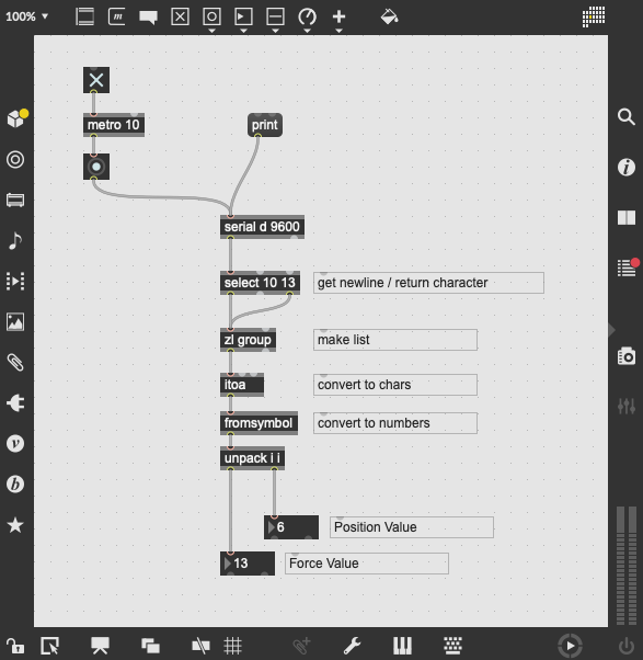
Figure: Max patch for receiving the two sensor values.