
A First Arduino-Sensor-Circuit
The Arduino
For all examples in this section, the Arduino UNO is used. The documentation on the official Arduino website covers all details on the connection possibilities and many examples to get started. The most important bit of information for most tutorials and basic applications is the pinout map:
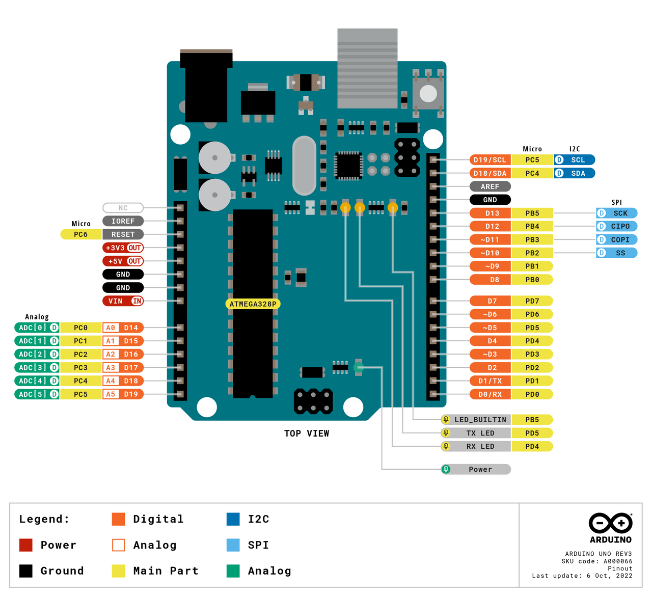
Arduino pinout (https://docs.arduino.cc/).
Besides power and ground pins, the following connections are of interest for these examples:
6 analog inputs (0-5V)
14 digital pins (in and output mode can be set for each pin)
5 PWM output pins
serial receive
serial transmit
The Sensor
This very first step shows how to use basic sensors with the Arduino. These sensors are variable resistors, which change their conductivity based on physical quantities. Examples are temperature, distance or force. The following examples us a light dependent resistor (LDR). The brighter the light it is exposed to, the lower its resistance.
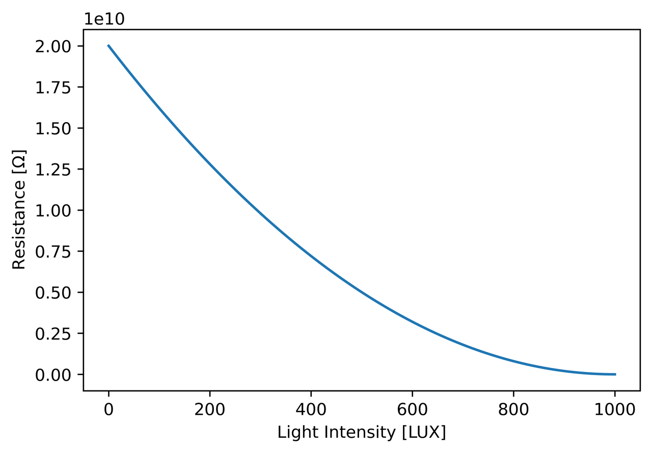
Figure: Approximated curve of the LDR in this example.
The Voltage Divider
In order to use the light dependent sensor in a measurement setup, a so called voltage divider is needed. It compares the variable resistor R1 (in this case the LDR) with a fixed resistor R2:
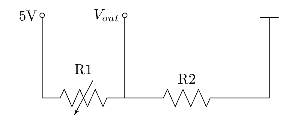
Figure: Voltage divider circuit.
For a full use of the voltage range, R3 needs to be chosen properly. The voltage measured at the output depends on the reference voltage of 5V and the ratio between the two resistors:
$$ V_{out} = 5V \frac{R_2}{R_1 + R_2} $$
Some components, like potentiometers and faders, have the voltage divider integrated and thus have three pins for connection. They do not require an additional resistor.
Breadboard Wiring
The above-shown circuit can be realized using all components, a mini breadboard and three jumper cables. The documentation on the original Arduino website (Getting Started with Arduino introduces the board with all its connection capabilities in detail. For this example, we need a small breadboard, the LDR, one resistor and three jumper cables. A $100 \Omega$ resistor is chosen. For first steps, the Arduino can be powered via USB, which will also be used to read the sensor data into the Arduino serial monitor.
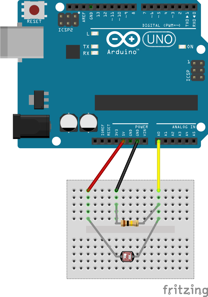
Figure: Arduino breadboard wiring.
Arduino Code
The easiest way to program an Arduino is the dedicated Arduino IDE, which is available for all major operating systems. Install and use instructions are thoroughly documented on the official Arduino website.
The Arduino code for testing this sensor circuit is minimalistic.
Like most Arduino sketches, basic setup is carried out in the setup() function on boot.
In this case, the serial interface is started with a baud rate (speed in symbols per second) of 9600 bauds.
Afterwards, the loop() function is carried out infinitely.
It reads the given voltage at the selected pin A0 and prints it to the serial output.
Follow the instructions on the Arduino website to upload the below code to your board. In general, the serial port of the board needs to be selected in the IDE's dropdown manual, alongside the Arduino model - in this case the Arduino UNO.
void setup() {

Serial.begin(9600);
}

void loop() {

int sensorValue = analogRead(A0);

Serial.println(sensorValue);

delay(5);
}
Without any manipulation, the values from the analogRead() function range from 0 to 1024,
since the Arduino analog-digital converters have 10 bit resolution:
$$ N = 2^{10} = 1024 $$