
Concept of Subtractive Synthesis
Functional Units
Subtractive synthesis is probably the best known and most popular method of sound synthesis. The basic idea is to start with signals with rich spectral content which are then shaped afterwards by filters. Although the possibilities of subtractive synthesis are quasi-unlimited, especially when combined with other methods, the principle can be explained with three groups of functional units:
Generators
Manipulators
Modulators
[Fig.1] gives an overview how these functional units are arranged in a subtractive synthesizer. Modulators and generators overlap, since they are interchangeable in many aspects. This section uses the terminology from the (modular) analog domain, with Voltage Controlled Oscillators (VCO), Voltage Controlled Filters (VCF) and Voltage Controlled Amplifiers (VCA).
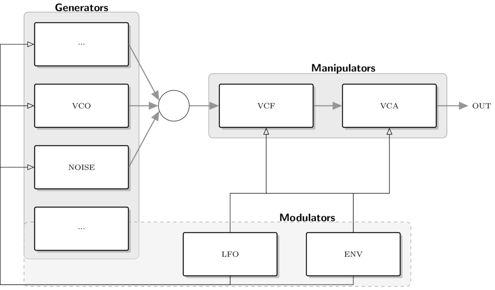
Functional units in subtractive synthesis.
Generators
Oscillators (VCO)
Noise Generators
...
Frequently used oscillators in subtractive synthesis are the basic waveforms with high frequency energy, such as the sawtooth, square wave or the triangular wave (See the section on additive synthesis). Noise generators can be used for adding non-harmonic components.
Manipulators
Filters (VFC)
Amplifiers (VCA)
...
The most important manipulators are filters and amplifiers, respectively attenuators. Filters will be explained in detail in the following sections.
Modulators
LFO (Low Frequency Oscillators)
Envelopes (ADSR)
...
Modulators are such units which control the parameters of generators and manipulators over time. This includes periodic modulations, such as the LFO, and envelopes, which are triggered by keyboard interaction.
A Typical Bass/Lead Patch
Like with all methods for sound synthesis, the dynamic change of timbre is an essential target for generating vivid sounds. [Fig.2] shows a more specific signal flow which is a typical subtractive synth patch for generating lead or bass sounds.
The signal from a VCO is manipulated by a VCF and then attenuated by a VCA.
The VCO has a sawtooth or square waveform.
The cutoff frequency of the VCF and the amplitude of the VCA are controlled with individual envelopes.
If ENV2 has a faster decay than ENV1, the sound will have a crisp onset and a low decay, resulting in the typical thump.
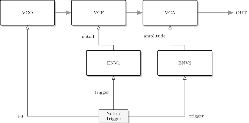
Subtractive patch for bass and lead synth.