Envelopes: ADSR

Envelopes are an essential part of control in electronic music and computer music. They are used to shape the characteristics of sound or other processes over time and are an integral part of synthesizers. Since they are that basic and versatile, they will be introduced in this early section.


One of the most common envelopes, already featured in early synthesizers and in prominent examples as the MiniMoog, is the ADSR envelope (Hiyoshi, 1979). It is comprised of four segments:

  • Attack

  • Decay

  • Sustain

  • Release

Attack time, decay time and release time can usually be controlled by the user via dials or sliders, whereas the sustain time depends on the duration a key is pressed and the sustain level may depend on the stroke velocity. Depending on the settings, the ADSR model can generate amplitude and timbral envelopes for slowly evolving sounds like strings or sounds with sharp attacks and release:

Your browser does not support the HTML5 canvas tag

Attack Time:

Decay Time:

Sustain Level:

Sustain Time:

Release Time:


When used in synthesizers, this envelope can be used to control the overall level or the timbre - for example through the cutoff frequency of a filter or by means of partial amplitudes.


References

1979

  • Teruo Hiyoshi, Akira Nakada, Tsutomu Suzuki, Eiichiro Aoki, and Eiichi Yamaga. Envelope generator. December 18 1979. US Patent 4,178,826.
    [details] [BibTeX▼]

Working with Groups

Creating Groups

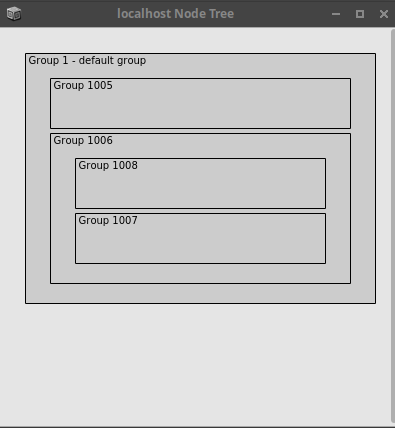
Groups - or group nodes - can be a very useful concept for keeping track of the signal flow. Without any further actions, all nodes are placed in the default Group 1. Additional groups can be arranged regarding the order of execution. A new group can be added from sclang as follows:

~g1 = Group.new();

Adding Nodes to Groups

Synth nodes can be added to groups on creation or afterwards. Any existing node - in this case the ~osc node from the previous example <http://ringbuffer.org/computer_music_basics/SuperCollider/combining-nodes-in-supercollider/> - can be moved to a group using the following commands:

// make it the first node in the group
~osc.moveToHead(~g1)

// make it the last node in the group
~osc.moveToTail(~g1)

Relative Group Positions

As with nodes, further groups can be added in relation to existing groups. The following action makes sure that a new group will be placed after the previously defined group:

~g2 = Group.after(~g1);

Nested Groups

Groups can contain other groups, allowing a hierarchical structure of nodes:

~g3 = Group.head(~g2);

More on Groups

The group object allows many more actions. They are listed in the SC documentation on groups. After adding another group before the third one

~g4 = Group.before(~g3);

the server node structure looks as follows:

/images/basics/sc-group-nodes.png

The server does not know the groups by their variable names in sclang. Hence they are numerated. Node indices - or IDs - of groups can be assessed from the language:

~g1.nodeID;
~g2.nodeID;
~g3.nodeID;
~g4.nodeID;

Exercise

Pure Data: Installing Externals with Deken

The basic install of PD is referred to as Vanilla. Although many things are possible with this plain version, some additional libraries are very helpful and there is a handful which can be considered standard.

Find and Install Extensions

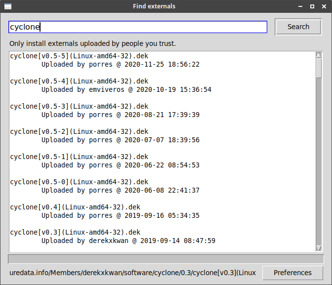
PD comes with Deken, a builtin tool for installing external libraries. Deken can be opened from the menu of the PD GUI. On Linux installs it is located under Help->Find Externals. Deken lets you search for externals by name. The best match is usually found at the top of the results. cyclone is an example for a library with many useful objects:

/images/basics/pd-deken-1.png

Deken lets you select where to install externals in its Preferences menu. Everything will be located in the specified directory afterwards.


Add Libraries to Search Paths

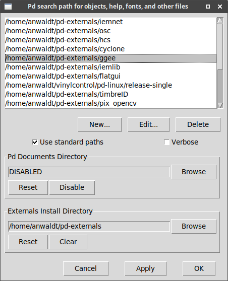
Once installed, it may be necessary to add the individual libraries to the search paths. This is done in an extra step. On Linux installs, this can be found under Edit->Preferences->Path:

/images/basics/pd-deken-2.png

Digital Waveguides: Ideal String without Losses

Ideal String with two Delay Lines

Based on the previously introduced discrete solution for the wave equation, an ideal, lossless string can be implemented using two delay lines with direct coupling. The left-traveling and right-traveling wave are connected end-to-end. Output samples of each delay line are direcly inserted to the input of the counterpart:


The Excitation Function

The waveguides can be initiated - or excited - with any arbitrary function. This may vary, depending on the excitation principle of the instrument to be modeled. For a plucked string, the excitation can be a triangular function with a maximum at the plucking point $p$. Both waveguides (left/right travelling) are initiated with the same function:

$$y[i] = \begin{cases} \frac{i}{p} & \mbox{for } i \leq p \\ 1-\frac{i-p}{N-p} & \mbox{for } i > p \\ \end{cases}$$
    

Oscillation

When both waveguides are shifted by one sample each $\frac{1}{f_s}$ seconds, the ideal string is oscillating with a frequency of $f_0 = \frac{f_s}{N}$. It will oscillate continuously. In fact it is a superimposition of two oscillators with the waveform defined by the excitation function.


Once Loop Reflect

Faust: Delay

Unit Delay

A unit sample delay can be used with the ' operator. This very basic operation is used in standard building blocks like integrators or digital filters.


Integer Delay

The integer delay can be controlled during processing. This example uses a horizontal slider for controlling the delay. Original and delayed signal are sent to the left and right output for testing the effect.

Load the example in the Faust online IDE for a quick start:

text


import("stdfaust.lib");

// get the sample rate
SR    = fconstant(int fSamplingFreq, <math.h>);
delay = hslider("Delay[samples]",0, 0, 10000, 1);

sig = os.lf_saw(1);

process =  sig <: _,(_ , delay : @);

Fractional Delay

Integer delays can only shift the signal by multiples of the inverse sampling frequency. Fractional delays can also shift the signal by non-integer values. The Faust delay library contains multiple implementations.

FM Synthesis: Formula & Spectrum

FM Formula

Frequency modulation with two sinusoidal oscillators can be written as follows:

$$ x(t) = A \sin(\omega_\alpha t + I \sin(\omega_\beta t) ) $$

Modulation Index:

$$I = \frac{\Delta f}{\Delta f_m}$$

Spectrum of Frequency Modulation

Compared to amplitude modulation techniques, FM generates more spectral components, which can be illustrated when calculating the Fourier transform of the FM formula.

Based on the FM formula, the spectrum can be calculated using trigonometric identities:

$$ x(t) = \cos(\omega_\alpha t + I \sin(\omega_\beta t) ) $$

$\text{with:} \cos(a+b) = \cos(a) \cos(b) - \sin(a) \sin(b)$

$$ x(t) = \cos(\omega_\alpha t) \cos(I \sin(\omega_\beta t)) - \sin(\omega_\alpha t) \sin(I \sin(\omega_\beta t)) $$

$\text{with:} \cos(a) \cos(b) = \frac{1}{2} \left( \cos(a-b) + \cos(a+b) \right)$

$\text{and:} \sin(a) \sin(b) = \frac{1}{2} \left( \cos(a-b) - \cos(a+b) \right)$

$$ \begin{eqnarray} &=& \frac{1}{2} ( \sin(\omega_\alpha t + I \sin(\omega_\alpha t)) \\ &&+ \sin(\omega_\alpha t - I \sin(\omega_\alpha t))\\ &&+ \sin(\omega_\alpha t + I \sin(\omega_\alpha t)) \\ &&+ \sin( I \sin(\omega_\alpha t) - \omega_\alpha t) ) \end{eqnarray} $$

Bessel functions

The above equation can be expressed through Bessel functions:

$$ \begin{eqnarray} \sin(\omega_\alpha t + I \sin(\omega_\alpha t)) &=& J_0(I) \cos(\omega_\alpha) \\ % && + J_1(I) \cos(\omega_\alpha - \omega_\beta)t - \cos(\omega_\alpha + \omega_\beta)t \\ % && - J_2(I) \cos(\omega_\alpha - 2 \omega_\beta)t + \cos(\omega_\alpha + 2 \omega_\beta)t \\ % && + ... \end{eqnarray} $$

The spectrum of FM signals thus has an infinite number of sidebands which are increased in energy for high modulation indices.


Harmonic vs Inharmonic

Depending on the ratio between modulator and carrier, the FM spectrum has different properties. In the formula for the FM sidebands is is obvious that for integer ratios between carrier to modulator, all sidebands are integer multiples of the fundamental frequency.

Additive & Spectral: Spectral Modeling

McAulay/Quatieri

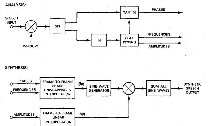
Sinusoidal modeling can be considered a higher level algorithm for the additive synthesis of harmonic sounds. It has first been used in speech processing by McAulay, R. and Quatieri (1986). For low framerates they proposed a time-domain method for partial synthesis with original phases of the partials.

/images/Sound_Synthesis/spectral_modeling/quatieri_system.jpg

R. McAulay and T. Quatieri (1986)


SMS

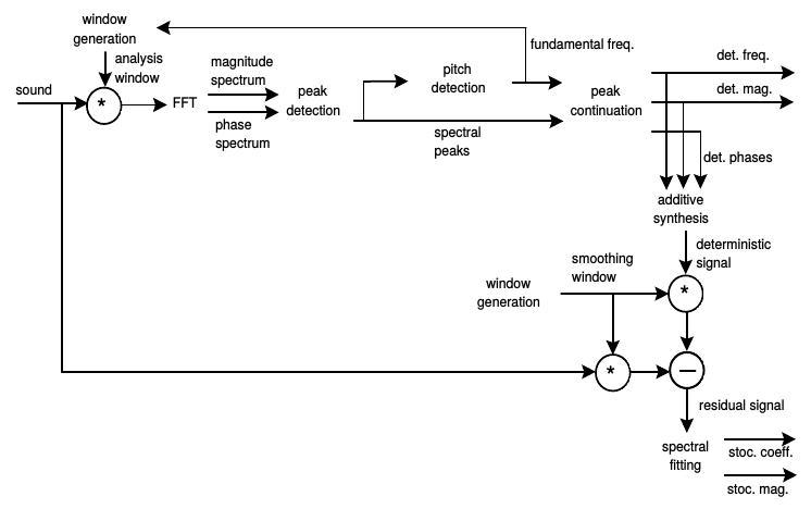
The above presented sinusoidal modeling approach captures only the harmonic portion of a sound. With the Sinusoids plus Noise model (SMS), Serra and Smith (1990) introduced the Deterministic + Stochastic model for spectral modeling, in order to model components in the signal which are not captured by partial tracking. A sound is therefor modeled as a combination of a dererministic component - the sinusoids - and a stochasctic component:

\begin{equation*} x = x_{DET} + x_{STO} \end{equation*}
/images/Sound_Synthesis/spectral_modeling/sines_plus_noise_block.jpg

Deterministic + Stochastic model (Serra and Smith, 1990)

Violin Example

The following example shows the sines + noise decomposition for a single violin sound. The original recording was made in an anechoic chamber:

After partial tracking, the deterministic component can be re-synthesized using an oscillator bank. It features the strings oscillation, in this case with original phases. For a bowed string instrument like the violin, the deterministic model alone can deliver plausible results:

The residual signal still carries some parts of the deterministic part, when calculated with simple subtraction. Most of the residual's energy is caused by the bow friction:


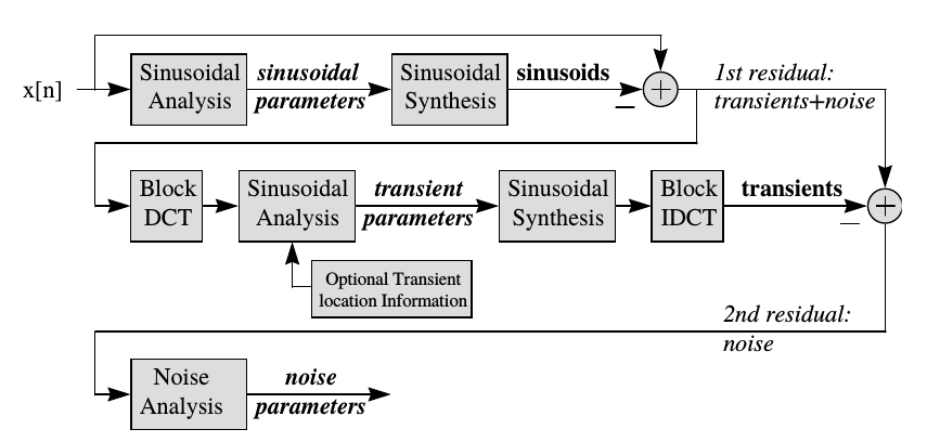
Sines + Transients + Noise

Even the harmonic and noise model can not capture all components of musical sounds. The third - and in this line last - signal component to be included are the transients.

/images/Sound_Synthesis/spectral_modeling/sin-trans-noise.png

Sines + Transients + Noise (Levine and Smith, 1998)


References

2007

  • Arturo Camacho. Swipe: A Sawtooth Waveform Inspired Pitch Estimator for Speech and Music. PhD thesis, University of Florida, Gainesville, FL, USA, 2007.
    [details] [BibTeX▼]

2005

2002

  • Alain de Cheveigné and Hideki Kawahara. YIN, a Fundamental Frequency Estimator for Speech and Music. The Journal of the Acoustical Society of America, 111(4):1917–1930, 2002.
    [details] [BibTeX▼]

1998

1990

1986

  • R. McAulay and T. Quatieri. Speech analysis/Synthesis based on a sinusoidal representation. Acoustics, Speech and Signal Processing, IEEE Transactions on, 34(4):744–754, 1986.
    [details] [BibTeX▼]
  • T Quatieri and Rl McAulay. Speech transformations based on a sinusoidal representation. IEEE Transactions on Acoustics, Speech, and Signal Processing, 34(6):1449–1464, 1986.
    [details] [BibTeX▼]

Faust: OSC Control

For standalone standalone and embedded plugins, OSC control can be a useful option. Faust compiles with OSC functionality with the -osc flag:

$ faust2jaqt -osc sine.dsp

Starting the program in the command line gives information on the standard faust OSC ports:

$ ./sine
Faust OSC version 1.22 - 'sine' is running on UDP ports 5510, 5511, 5512, sending on localhost

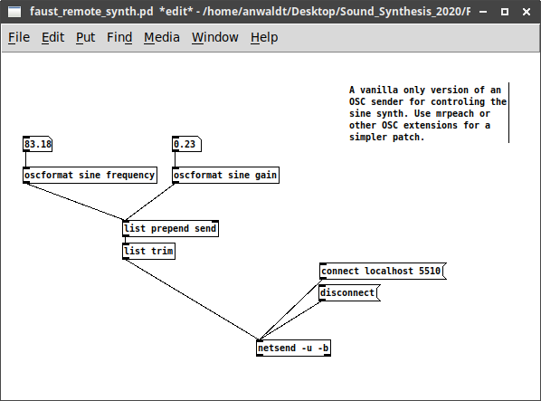
The running program can now be controlled through any OSC sender, using the proper IP address, port and paths:

/images/Sound_Synthesis/sine_osc_example.png