Wavetable Oscillator with Phase Reset

The Faust oscillators.lib comes with many different implementations of oscillators for various waveforms. At some point one might still need a behavior not included and lower level approaches are necessary.

This example shows how to use a phasor to read a wavetable with a sine waveform. This implementation has an additional trigger input for resetting the phase of the oscillator on each positive zero crossing. This can come handy in various applications, especially for phase-sensitive transients, as for example in kick drums.

The example is derived from Barkati et. al (2013) and part of the repository:

import("stdfaust.lib");

// some basic stuff
sr = SR;
twopi = 2.0*ma.PI;

// define the waveform in table
ts =  1<<16; // size = 65536 samples (max of unsigned short)
time = (+(1) ~ _ ) , 1 : - ;
sinewave =  ((float(time) / float(ts)) * twopi) : sin;

phase = os.hs_phasor(ts,freq,trig);

// read from table
sin_osc( freq) = rdtable(ts ,sinewave , int(phase)) ;

// generate a one sample impulse from the gate
trig =  pm.impulseExcitation(reset);

reset = button ("reset");
freq = hslider("freq", 100, 0, 16000, 0.00001);

// offset = hslider("offset", 0, 0, 1, 0.00001);

process = sin_osc(freq);

2013

  • Karim Barkati and Pierre Jouvelot. Synchronous programming in audio processing: a lookup table oscillator case study. ACM Computing Surveys (CSUR), 46(2):1–35, 2013.
    [details] [BibTeX▼]

Controlling SC with the Mouse

A quick way of control is often needed when testing and designing synthesis and processing algorithms in SuperCollider. One quick way is to map the mouse position to control rate buses. Combined with a touch display, this can even be an interesting means for expressive control. This example first creates a control bus with two channels. The node ~mouse uses the MouseX and MouseY UGens to influence the two channels of this bus:

// mouse xy controll with busses
~mouse_BUS = Bus.control(s,2);

~mouse   = {
  Out.kr(~mouse_BUS.index,   MouseX.kr(0,1));
  Out.kr(~mouse_BUS.index+1, MouseY.kr(0,1));
}.play;

Exercise

Additive & Spectral: IFFT Synthesis

The calculation of single sinusoidal components in the time domain can be very inefficient for a large number of partials. IFFT synthesis can be used to compose spectra in the frequency domain.

/images/Sound_Synthesis/ifft/ifft-0.png

Main lobe kernel for \(\varphi = 0\)

/images/Sound_Synthesis/ifft/ifft-1.png

Main lobe kernel for \(\varphi = \pi/2\)

/images/Sound_Synthesis/ifft/ifft-2.png

Main lobe kernel for \(\varphi = \pi/4\)

/images/Sound_Synthesis/ifft/ifft-3.png

Main lobe kernel for \(\varphi =c3 \pi/4\)

The Smart Mesh

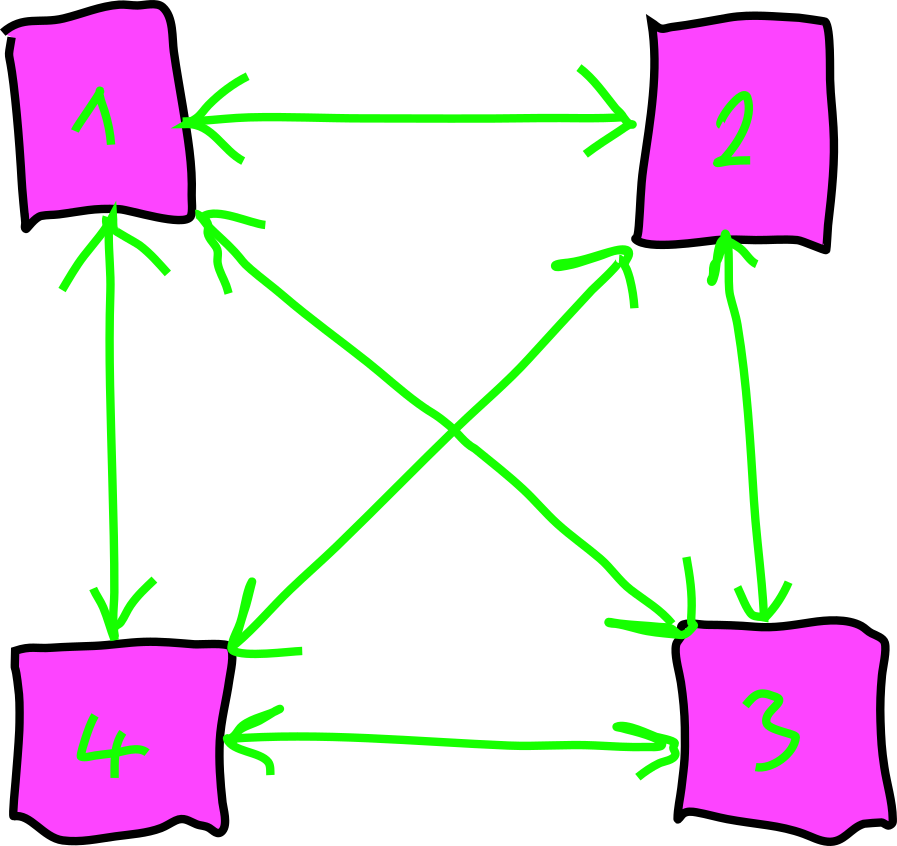
The Smart Mesh is an extension of the simple mesh. It creates a fully connected, flexible mesh audio network, using JackTrip:

/images/mis/mesh_2.png

Four Access Points in a 'smart' mesh.

In this configuration, audio signals can be sent from every node to every node with a specific gain. Each of the Access Points [1,2,3,4] can manage where to send signals and which signals to receive.


Step 1: Launch Jack with Autoconnect Restrictions

In order to be in full control of the Jack-connections, we need to add the following flags to restrict all autoconnect requests from new clients:

$ jackd -a a .....additional arguments.....

Read the section on using JACK Audio for the full list of arguments we need.


Step 2-3: Follow the Simple Mesh Example

Follow all steps in the Simple Mesh example to get the JackTrip server and clients running on the APs.


Step 4: The SC Mixer

To route signals from each AP to al other APs, we need to increase the number of SC input and output buses needs to be increased. With N=11 peers we want N outputs - one to the speaker the PI is connected to, and one output to each JackTrip client:

s.options.numOutputBusChannels = 12;
s.options.numInputBusChannels = 12;

The Control Buses

After booting the local server, we create a NxN control-bus routing matrix. This is realized through an array of multichannel buses:

~gain_BUS = Array.fill(12,{Bus.control(s,12)})

The Send-SynthDef

This SynthDef takes one input signal (from JackTrip or the analog input) and routes it to all outputs with individual gains:

SynthDef(\mesh_send,{
    |
    inbus,
    outbus,
    gainbus
    |
    Out.ar(outbus, SoundIn.ar(Array.fill(12,inbus)) * In.kr(gainbus,12));
}).send;

As shown in the following figure, the mesh_send is only prcessing one input:

/images/mis/mesh_send.png

Signal flow for the mesh_send with 4 APs.

The Mixer

Our mixer consists of multiple Send-Synths - one for each input signal. We create an array of N=12 mesh_sends, each with the proper index for input and control bus. Every send node will get an individual input and an individual element from ~gain_BUS - but they all output their signals to the same 12 outputs of SC:

~mixer = Array.fill(12,{arg i;
    i.postln;
    Synth(\mesh_mixer,[
        \inbus  ,i,
        \outbus ,0,
        \gainbus,~gain_BUS[i]
    ]);
});

Step 5: Connecting the Jack-Clients

If the SC server has been properly cofigured and booted, the JackTrip clients can be connected. The following image shows the connections on AP1 for a total of 4 Access Points:

/images/mis/smart_mesh_jack.png

Jack routings for a smart mesh with 4 APs.


Step 6: Set Routing Gains

Once all components are running and everything has been connected, the values of the control buses on each node can be set, to create all possible forms of configurations. Since there is no aditional processing (delay, feedback, ...) in the chain, we have to avoid feedbacks.

If AP1 from the previous figure wants to send its local audio input (mic, instrument) to AP2, the following bus gains have to be set:

~gain_BUS[0].setAt(1,1);

If AP1 wants to send its local input to all other nodes and the local output (loudspeaker), it can use the following command:

~gain_BUS[0].setAll(1);

Using Envelopes

The body of a basic electronic kick drum is a sine wave with an exponential decrease in frequency over time. Depending on the taste, this drop happens from about 200-300 Hz to 30-60 Hz. This can be achieved with temporal envelopes.

Define Envelopes

Before using an envelope, it needs to be defined, using the Env class. It is feature rich and well documented insice the SC help files. The following line creates an exponential envelope with a single segment, defining an exponential drop. It can be plotted using the envelope's plot method:

~env = Env([1, 0.1], [0.15], \exp);
~env.plot;

/images/basics/sc-envelope.png

---

Using an Envelope Generator

Envelopes can be passed to envelope generators. The following example generates a control rate signal with the exponential characteristics. It will be sent to the control bus with the index 0 (Out.kr(0,)) and the created node will be freed once the envelope is done, defined by the done action. The bus can be monitored to see the result:

s.scope(1,0,rate:'control')

{Out.kr(0,EnvGen.kr(~env, doneAction: Done.freeSelf))}.play

A "Kick" SynthDef

The following SynthDef uses the envelope inside the node. No bus is needed for The synth has two arguments - the gain and the pitch:

(
SynthDef(\kick,
{
    |gain=1,pitch=100|

    var env = EnvGen.kr(~env, doneAction: Done.freeSelf);

    // send the signal to the output bus '0'
    Out.ar(0, gain*SinOsc.ar(env*pitch));
};
).send(s)
)

Triggering it

The SynthDef can now be used to create a node on the server. It receives two arguments for gain and pitch:

Synth(\kick, [1,300])

Once the envelope is finished, the '''Done.freeSelf''' will remove the whole node from the server. When multiple envelopes are used within a node, the first one to finish will free the node, if set to '''doneAction: Done.freeSelf'''. Other doneActions can help prevent this ('''Done.none''').


Exercise

Laplace Transform

Managing Jack Connections

When JackTrip clients connect corresponding jack clients are created on the server side that may have a name defined by the connecting client. In the SPRAWL system every client connects with a remote name that starts with AP_ followed by the user's name. Those jack clients must be connected to the right inputs and outputs of the sprawl system. There are several solution to do this automatically. With aj-snapshot you can create a snapshot of all current jack connections and reconnect that state later. You can even running aj-snapshot as a daemon to constantly watch that all connections of a snapshot are set.

In the sprawl system we don't know the full name of connecting jacktrip clients. With jack-matchmaker we are able to write pattern files that use regular expressions to connect jack clients:

#
# Direct Input

/AP_.*_1:receive_1/
   SPRAWL_Server:in_1
/AP_.*_1:receive_2/
   SPRAWL_Server:in_2
/AP_.*_2:receive_1/
   SPRAWL_Server:in_3
/AP_.*_2:receive_2/
   SPRAWL_Server:in_4

Those regexes in slashes are conforming `python's regex syntax <https://docs.python.org/3/library/re.html>'_. Jack-Matchmaker can show you all current connections:

$ jack-matchmaker -c
AP_Nils_1:receive_1
    SPRAWL_Server:in_1

SPRAWL_Server:out_1
    AP_Nils_1:send_1

SPRAWL_Server:out_2
    AP_Nils_1:send_2

SPRAWL_Server:out_33
    AP_Nils_1:send_1

SPRAWL_Server:out_34
    AP_Nils_1:send_2

As you see I'm sending one audio channel to the server that connects to the first input of the SPRAWL_Server SuperCollider application. The next two connections are the direct outputs to my receiving channels. The last two connections are the binaural rendered spatialised mix.

Jack-Matchmaker user service

Right now the jack-matchmaker user service loads the pattern file located in /home/student/SPRAWL/matchmaker/sprawl_server_stereo.pattern. This might be changed in the future with a template instantiated service.

Physical Modeling: Advanced Models

More advanced physical models can be designed, based on the principles explained in the previous sections.


Resonant Bodies & Coupling

The simple lowpass filter in the example can be replaced by more sophisticated models. For instruments with multiple strings, coupling between strings can be implemented.

/images/Sound_Synthesis/physical_modeling/plucked-string-instrument.png

Model of a wind instrument with several waveguides, connected with scattering junctions (de Bruin, 1995):

/images/Sound_Synthesis/physical_modeling/wind_waveguide.jpg

References

2019

  • Stefan Bilbao, Charlotte Desvages, Michele Ducceschi, Brian Hamilton, Reginald Harrison-Harsley, Alberto Torin, and Craig Webb. Physical modeling, algorithms, and sound synthesis: the ness project. Computer Music Journal, 43(2-3):15–30, 2019.
    [details] [BibTeX▼]

2004

  • Chris Chafe. Case studies of physical models in music composition. In Proceedings of the 18th International Congress on Acoustics. 2004.
    [details] [BibTeX▼]

1995

  • Vesa Välimäki. Discrete-time modeling of acoustic tubes using fractional delay filters. Helsinki University of Technology, 1995.
    [details] [BibTeX▼]
  • Gijs de Bruin and Maarten van Walstijn. Physical models of wind instruments: A generalized excitation coupled with a modular tube simulation platform*. Journal of New Music Research, 24(2):148–163, 1995.
    [details] [BibTeX▼]

1993

  • Matti Karjalainen, Vesa Välimäki, and Zoltán Jánosy. Towards High-Quality Sound Synthesis of the Guitar and String Instruments. In Computer Music Association, 56–63. 1993.
    [details] [BibTeX▼]

1992

  • Julius O Smith. Physical modeling using digital waveguides. Computer music journal, 16(4):74–91, 1992.
    [details] [BibTeX▼]

1971

  • Lejaren Hiller and Pierre Ruiz. Synthesizing musical sounds by solving the wave equation for vibrating objects: part 1. Journal of the Audio Engineering Society, 19(6):462–470, 1971.
    [details] [BibTeX▼]
  • Lejaren Hiller and Pierre Ruiz. Synthesizing musical sounds by solving the wave equation for vibrating objects: part 2. Journal of the Audio Engineering Society, 19(7):542–551, 1971.
    [details] [BibTeX▼]

FM Synthesis: DX7

FM synthesis was not only an outstanding method for experimental music but landed a major commercial success. Although there are many more popular and valuable synthesizers from the 80s, no other device shaped the sound of pop music in that era like the DX7 did. It was not the first ever, but the first affordable FM-capable synth and can generate a wide variety of sounds -- bass, leads, pads, strings, ... -- with extensive (but complicated) editing opportunities. It was also the breakthrough of digital sound synthesis, using the full potential with MIDI.

/images/Sound_Synthesis/modulation/yamaha_dx7_angle2.jpg
[Fig.1]

Yamaha DX7.

Specs

  • released in 1983

  • 16 Voices Polyphony

  • 6 sine wave 'operators' per voice

  • velocity sensitive

  • aftertouch

  • LFO

  • MIDI

The DX7 in 80s Pop

Tina Turner - What's Love Got To Do With It

  • 1984

  • blues harp preset

  • starting 2:00

https://youtu.be/oGpFcHTxjZs

Laura Branigan - Self Control

  • 1984

  • the bells

https://youtu.be/WqiCQA8ROXU

Harold Faltenmeyer - Axel F

  • 1986

  • marimbas

  • starting 1:40

https://youtu.be/V4kWpi2HnPU

Kenny Loggins - Danger Zone

  • 1986

  • FM bass

https://youtu.be/siwpn14IE7E

A Comprehensive List

Find a comprenesive list of famous examples, here:

http://bobbyblues.recup.ch/yamaha_dx7/dx7_examples.html

Programming the DX7

The DX7 can be fully programmed using membrane buttons. Alternatively, Sysex messages can be used to work with external programmers, like a laptop, over MIDI. For users new to FM synthesis, it may be confusing not to find any filters. Timbre is solely controlled using the FM parameters, such as operator freuqncy ratios and modulation indices.

Algorithms

The configuration of the six operators, respectively how they are connected, is called algorithm in the Yamaha terminology. In contrast do some of its successors, the DX7 does not allow the free editing of the operator connections but provides a set of 32 pre-defined algorithms, shown in [Fig.2].

/images/Sound_Synthesis/modulation/dx7-1.jpg
[Fig.2]

Yamaha DX7 manual: algorithm selection.

Envelopes

For generating sounds with evolving timbres, each operator's amplitude can be modulated with an individual ADHSR envelope, shown in [Fig.3]. Depending on the algorithm, this directly influences the modulation index and thus the overtone structure.

/images/Sound_Synthesis/modulation/dx7-2.jpg
[Fig.3]

Yamaha DX7 manual: envelope editing.

Velocity

The level of each operator, and therefor modulation indices, can be programmed to depend on velocity. This allows the timbre to depend on the velocity, as in most physical instruments, which is crucial for expressive performances.

FM Synthesis: Pure Data Example

The following Pure Data example shows a 2-operator FM synthesis with two temporal envelopes. This allows the generation of sounds with a dynamic spectrum, for example with a sharp attack and a decrease during the decay, as it is found in many sounds of musical instruments. The patch is derived from the example given by John Chowning in his early FM synthesis publication:

/images/Sound_Synthesis/modulation/fm-chowning-flow-2.png
[Fig.1]

Flow chart for dynamic FM with two operators (Chowning, 1973).


The patch fm_example_adsr.pd can be downloaded from the repository. For the temporal envelopes, the patch relies on the abstraction adsr.pd, which needs to be saved to the same directory as the main patch. This ADSR object is a direct copy of the one used in the examples of the PD help browser.

/images/Sound_Synthesis/modulation/pd-fm-envelope.png
[Fig.2]

PD FM Patch.