Patches and Subpatches in Pure Data

Arguments

The following examples are based on patches and additional files, called abstractions. To make them work, all involved patches need to be located in the same direction (by cloning the complete repository). Arguments are passed to objects after the name, separated by a white space. The patch arguments-help.pd shows this by creating an arguments object:

/images/basics/pd-arguments-1.png

Inside an abstraction, individual arguments can be accessed with the $ operator and their index. The loadbang is executed on the object's creation, thus printing both arguments on start. This is helpful for setting initial values in patches, as shown in arguments-help. Once created, it will print the arguments to the main Pd window:

/images/basics/pd-arguments-2.png

Subpatches

Subpatches can be very helpful for creating cleaner patches without addtional abstractions and files. To create a subpatch, use the object pd with an optional string argument for naming the subpatch. They can be used like abstractions but do not require an additional file.


Graph-on-Parent

When toggling Graph-on-Parent in an object's properties, it can expose GUI elements to its parent patch. This is a good way of cleaning your patch and showing only what is needed in a performance situation. It works for both abstractions and subpatches. The example patches.pd makes use of this to create a filter subpatch with controls. The left hand audio input of the suppatch is a fixed frequency sawtooth. The right hand control input sets the Q of the filter.

/images/basics/pd-patches-1.png

On the inside, the moog~ object is used. It is not part of PD vanilla and can be installed with the flatspace ggee extensions from Deken. The red rectangle marks the area visual in the parent patch. All GUI components inside this area will be visible:

/images/basics/pd-patches-2.png

Inlets and Outlets

The patch has two inlets - one in audio rate (inlet~) and one in control rate - and two outlets, also with audio rate (outlet~) and control rate. For inlets and outlets, their horizontal order determines their order in the object when patched from the parent. Changing them can mess up the complete patching.

FIR Filters

Finite Impulse Response (FIR) filters are such digital filters which have - as the name suggests - a finite impulse response. These filters do not have an internal feedback and can be applied simply by convolving an input sequence $x[n]$ with the filter's impulse response $h[n]$ to get the output sequence $y[n]$:

For FIR filters, the impulse response $h[n]$ is a one-dimensional array containing the $N$ filter coefficients. The following example shows the coefficients, respectively the impulse response for a filter of the order $N=5$:


The Difference Equation

From the impulse response we can get the coefficients $b_n$ to write the difference equation, which is the basis for applying a filter:

$$ y[n] = b_0 x[n] + b_1 x[n-1]+ b_2 x[n-2]+ b_3 x[n-3]+ b_4 x[n-4] + b_5 x[n-5] $$

Implementation Structure

Another important representation of a filter is the implementation structure. It can be directly derived from the difference equation. Each $z^{-1}$ block represents a delay by one sample. This case shows the direct form:


Applying a Filter by Convolution

Applying the filter with the given impulse response is done by simple convolution, which is the same as passing samples from the input of the implemtation structure above to its output. The above equation is then written as follows:

$$ \begin{eqnarray} y[m] &=& x[n] * h[m]\\ &=& \sum\limits_{m=0}^{M} h[m] x(n-m)\\ &=& \sum\limits_{m=0}^{M} b_m x(n-m)\\ \end{eqnarray} $$

The Transfer Function

The difference equation can also be expressed as a sum:

$$ h[n] = \sum\limits_{n=0}^{N} b_n x[n-1] $$

The transfer function of the filter can be obtained via the z-transform:

$$ H[z] = \sum\limits_{n=0}^{N} h[n] z^{-n} $$$$ H(z) = 0.5 z^{-2} + z^{-3} + 0.5 z^{-4} $$

In the next step, all exponents are shifted by expanding with $z^{4}$:

$$ H(z) = \frac{z^2 + 2z + 1}{z^4} $$

Factor the denominator to find its roots:

$$ H(z) = \frac{(z+1)(z+1)}{z^4} $$

There is a double zero at $\mathbf{z=-1}$. As all causal FIR filters it has $N=4$ poles at the origin $z=0$.

With $z=e^{j\omega}$ the complex roots can be obtained:

$$ Z = (e^{-i\omega} +1)(e^{-i\omega} +1) $$

In the Unit Cirlce

An LTI system can be visualized in the z-plane by plotting the zeros, respectively the roots of its impulse response.

Frequency Response

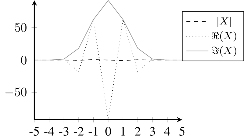
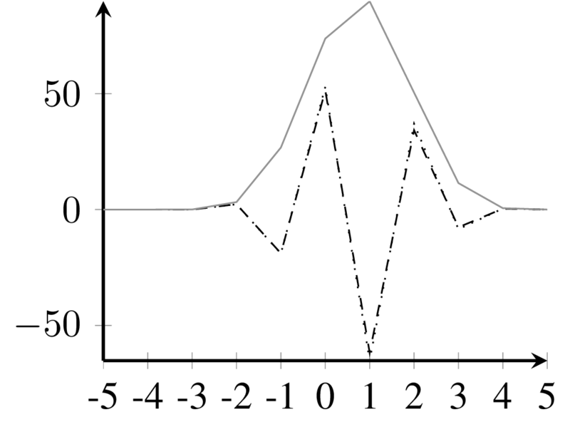
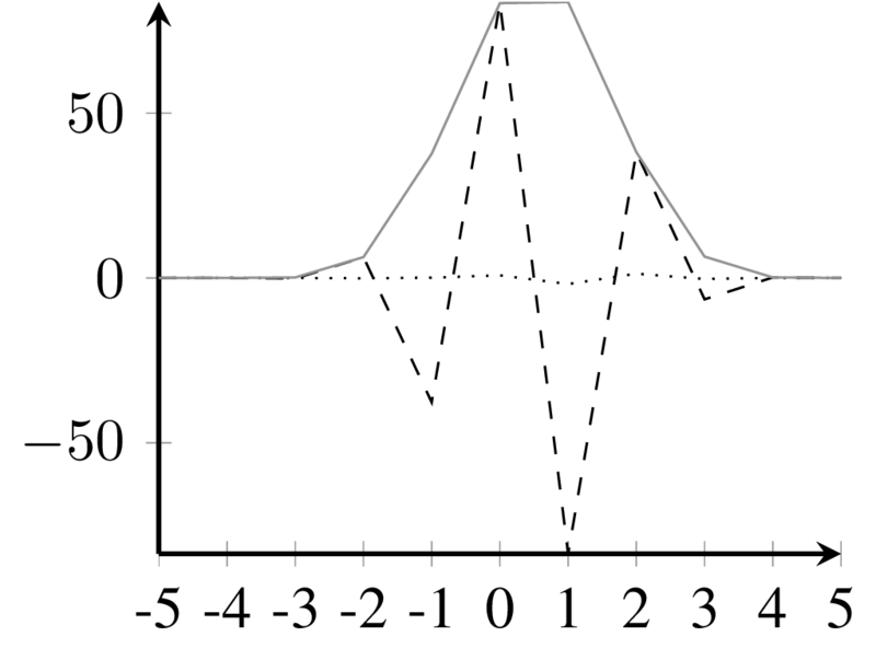
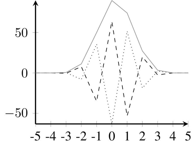
The frequency response of the filter

Controlling a Servo with Arduino

Servo motors are digitally controlled actuators, which allow the precise setting of angles via pulse-width encoding. Servos used in RC models are low-cost and easy to program, which makes them attractive for prototyping in sound art and other DIY projects. The following example is a copy of the original example at Arduino.


Breadboard Wiring

Connecting the servo motor to the Arduino requires no additional parts, except for jumper cables. It is directly powered from the Arduino's 5V pin (larger servos may require an additional power source) and receives data from the Pulse-With-Modulation pin ~9:

Arduino breadboard wiring for servo motor.

Arduino breadboard wiring for servo motor.


Arduino Code

The following code lets the sweep 180 degrees forward and backward, managed by two for loops (count up / count down) inside the main loop. Most consumer servos manage this range from 0 to 180 degrees and wrap exceeding values accordingly.

#include <Servo.h>

Servo myservo;
int pos = 0;

void setup() {
  myservo.attach(9);
}

void loop() {

  for (pos = 0; pos <= 180; pos += 1) {
    myservo.write(pos);
    delay(15);
  }

  for (pos = 180; pos >= 0; pos -= 1) {
    myservo.write(pos);
    delay(15);
  }
}

Exercise

Exercise

Combine the servo example with the sensor example to control the position 'manually'.

Diffusion

Following the tradition of Pierre Schaeffer, Diffusion refers to the live spatialization of tape music, respectively fixed media content. Typically, the music is played back in a low channel order (e.g. Stereo) and sent to a large number of loudspeakers using an 'inverted' mixing desk.

/images/spatial/natasha_villa.jpg

Natasha Barrett diffusing on a 3D system at a TU Studio concert (Villa Elisabeth, 2018).


The Acousmonium

The GRM (Groupe de Recherche Musicale) Acousmonium is an elaborate loudspeaker setup, designed for the diffusion of acousmatic music. It is made for touring and was first presented in Germany at the 1983 “Inventionen” festival by François Bayle. The system returned to Berlin for the 2008 edition of the SMC, where it was paired with the large WFS system at TU Berlin's H104:

/images/spatial/acousmonium_H104.JPG

The Acousmonium at TU Berlin (H104) during SMC 2008.


The BEAST

The Birmingham Electroacoustic Sound Theater (BEAST) is a modern version of the Acousmonium approach. It features 100+ loudspeakers in multiple groups with specific characteristics and purposes:

/images/spatial/beast_setup.JPG

Different loudspeakers of the BEAST system.

/images/spatial/beast_sketch.png

BEAST setup at CBSO Centre, Birmingham, May 2009 (Wilson, 2010).

The BEAST was presented in Berlin at the 2010 Inventionen Festival, when Jonty Harrisson was guest professor at TU Berlin. Read more in the online archive of the festival.

/images/spatial/BEAST_kirche.jpg

BEAST at Inventionen Festival 2008 (Elisabethkirche, Berlin).


References

2010

Using Arrays in SuperCollider

Simple Arrays

In SC, arrays are collections of objects of any kind. They can be defined and accessed using brackets:

// define simple arrays:
a = [0,1,2,3];
b = [0,1,2,"last_value"];

// access indices:
a[3];

Dynamic Creation

The array class offers numerous methods for creating arrays, including fill():

c = Array.fill(4,{arg i; 10/(i+1) });

Arrays of Buses

Especially in multichannel projects and larger mixing setups, arrays of buses can be helpful. Make sure to boot the server to actually use (scope) the buses:

// an array of 16 buses, each with 4 channels:
~busArray = Array.fill(16,{Bus.control(s, 4)})

// scope the second bus in the array:
~busArray[1].scope

// set the third bus of the second bus in the array:
~busArray[1].setAt(2,0.5);

Array of Nodes/UGens

The same array approach can be used to generate multiple nodes, for example sine waves at different frequencies and amplitudes:

// an array of 16 sine oscillators:
~sineArray = Array.fill(16,{arg i;{SinOsc.ar(200*i)}.play})

Array of Synths

The previous example can also be used with SynthDefs, which is a good starting point for additive synthesis:

// a simple synthdef
(
SynthDef(\sine,
{|f = 100, a = 1|

   Out.ar(0, a * SinOsc.ar(f));

}).send(s);
)

~busArray = Array.fill(16,{arg i;Synth.new(\sine,[f:200*(i+1),a:0.2])})

Warning

The second argument of fill has to be a function in curly brackets. If not, the array will contain multiple pointers to the same object (try)!